Oscilloscope Tab
Selecting the Hardware Configuration > Oscilloscope tab opens the following dialog. This dialog box can be used to configure the double-pulse test oscilloscope before running a DPT test.
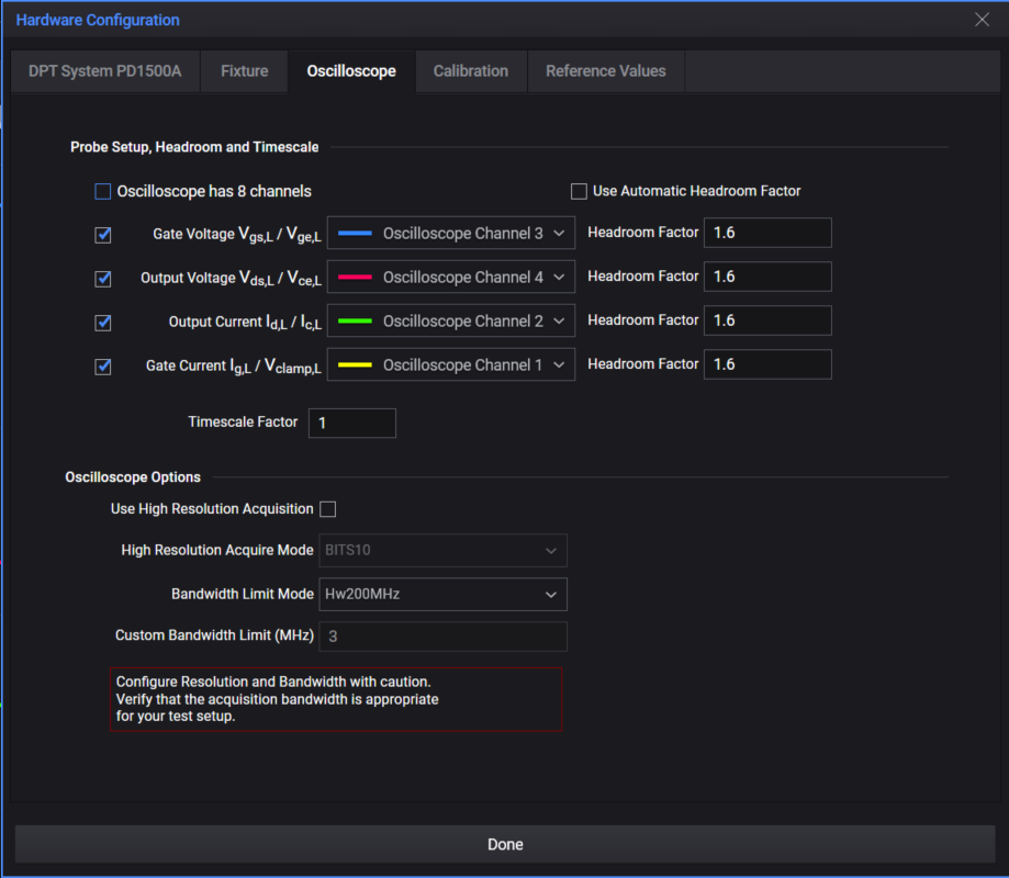
Probe Setup, Headroom, and Timescale
Oscilloscope has 8 channels: Depending on when you ordered the PD1500A and instrument availability at the time of order, you will receive either a DSOS104A 4-Channel oscilloscope or the MXR108A 8-Channel oscilloscope. Both oscilloscopes provide the same system performance. The MXR108A may be shipped with orders placed after February 2022. Except where indicated, installation and operation is the same for both oscilloscopes.
Refer to Oscilloscope Probe Setup for an explanation of the various probe locations.
- Gate Voltage VGS/VGE: Specify oscilloscope channel (Channel 1 through 4) for the Control Signal measurement. This is the Gate Voltage measured on the Low-Side Gate Drive Module by the N2873A 10:1 Oscilloscope Probe.
- Output Voltage VDS/VCE: Specify oscilloscope channel for the Output Voltage measurement. This is either the Source Voltage measured on the DUT Module with the 10076A 100:1 High Voltage Probe.
- Output Current ID/IC: Specify oscilloscope channel for Output Current measurement. This is the current measured across the Coaxial Shunt Resistor with the PD1000-60002 Oscilloscope Probe.
- Gate Current IG/VCLAMP: Specify oscilloscope channel for Gate current measurement IG or the VCLAMP measurement. IG is the current measured across the Gate Current Shunt Resistor (Low-Side Gate Drive Module) with the N2819A Differential Probe. VCLAMP is the Clamped Output Voltage measured with an N2873A 10:1 Oscilloscope Probe. NOTE: VCLAMP requires use of the Clamp Test Module (PD1000-66505).
The following settings are often helpful in debugging a Double-Pulse Test measurement. For detailed information, refer to the Keysight Infiniium Oscilloscopes Programmer’s Guide.
- Use Automatic Headroom Factor: Applies a factor to the y-axis of the Oscilloscope Capture display. When checked, the software detects clipping in the waveform and adjusts the vertical scale. Default for all oscilloscope channels is 1.6. Alternately, you can specify the headroom factor for each channel separately. For many GaN devices, the Headroom Factor should be set to 2 or as high as 3.6 or higher.
- Timescale Factor: Applies a factor to the x-axis of the Oscilloscope Capture display. Default is 1.0
Oscilloscope Options
- Use High Resolution Acquisition: Turns on (box is checked) or off (box is unchecked) the Infiniium oscilloscope’s High Resolution Acquisition Mode. (Normal Acquisition is the default.).
- High Resolution Acquire Mode: If the Use high resolution acquisition is turned on, sets the mode for the oscilloscope’s high resolution data acquisition – BITS10 (default), BITS11, BITS12, BITF13, and BITF14. This determines the minimum number of vertical resolution bits which affects the sampling rate. Do not use BITF13 or BITF 14; they are not applicable to the bandwidth of the oscilloscope.
- Bandwidth Limit Mode: Sets the bandwidth limit mode – Hw200MHz (default), Hw20MHz, Custom, or Off – for the oscilloscope’s input channel’s low-pass filter.
- Custom Bandwidth Limit (MHz): Minimum value is 1 kHz; maximum value is (sample rate)/2. This field is editable only when Bandwidth limit mode is set to Custom.
-- Evaluating Oscilloscope Bandwidths for your Application
-- Understanding Oscilloscope Frequency Response and its Effect on Rise-Time Accuracy.